FlexModul
Seasonal storage of solar energy


This research project has been completed. Download the FlexModul Publishable Final Report here.
The volatility (fluctuations) of renewable energies results in a high demand for energy storage. This is the only way to ensure a secure supply even at times of low energy production. In the future, heat storage systems will therefore play an important role in the integration of renewables and waste heat into energy systems. Their considerable flexibility and compensation potential make them particularly well suited for this. It ensures that the storage system can absorb excess energy from renewable heat and electricity sources and release it again in times of high heat demand. This balances out load peaks in renewable energy production and consumption and relieves the network.
Objective of the FlexModul project
The aim of the FlexModul project was the development and demonstration of an innovative, modular and compact sorption storage system; a so-called thermochemical storage. This technology is characterized above all by its high energy storage density and flexibility, low losses and simple, safe handling for building applications. Investment costs should be reduced to a minimum and the applicability of the concept should be maximized. Due to its modular structure, a sorption storage system is easily scalable and adaptable to various applications in the heating and electricity sector. The enormous potential of thermal storage as a cross-sectional technology becomes clear: the flexibility of the entire energy system is increased significantly, and CO₂ emissions are significantly reduced. Long-term storage is possible with almost no loss.
Approach and methodology of the FlexModul project
The project was divided methodologically into four central areas of work:
Figure 1: Overview of the methodological approach in the project, Source: FlexModul Final Report
A key objective was to raise the storage system to a higher TRL while simultaneously reducing manufacturing costs. The following methods were used to achieve this objective:
Building on previous projects involving sorption technology, numerous expert discussions were held on various development topics. In addition to the project partners, experts from IGTE University of Stuttgart and TU Berlin, as well as from the companies SorTech and ZeoSys, also took part.
- Component and System Development
- Extensive research into material selection was carried out at the AEE INTEC materials testing facility. The various sorption materials were examined in particular for mechanical and chemical stability, good and rapid water absorption capacity, sufficiently high temperature levels during discharge and good performance.
- Conceptual design, construction and simulation: Methods such as expert discussions, patent searches, SWOT analyses, 3D CAD designs, FEM simulations and simulation environments such as TRNSYS and Dymola were primarily used here.
- Manufacturing
- Process for mass production and economies of scale in production costs.
- Business Models / Dynamic economic analysis
- Based on the measurement results, a detailed simulation model was developed in MS Excel, whose core components were validated using the Simulation Studio (TRNSYS) simulation environment.
- Energy efficiency calculations and assessment based on selected KPIs.
- System Control & Integration
- Development of regulatory strategies and definition of operating modes using Modelica and TRNSYS.
- Demonstrator
- Functional verification of components and overall system by setting up a complete FlexModul system in the laboratory. Methods: measurement concept, sensor selection, data recording and transmission, measurement data visualisation, measurement data analysis, optimisation, comparison with simulation.
Technological pioneering role
The thermochemical storage systems mentioned have the potential to achieve three to four times higher energy densities compared to water storage systems. Energy is also efficiently stored over a long storage period (seasonal). So far, neither national nor international developments have been able to be launched on the market in this area. The technology used in the FlexModul project has already been successfully tested in previous projects. The project now combined numerous technological improvements at various levels in order to successfully complete the last development work up to the market launch and thus take on a technological pioneering role nationally and internationally.
The main objective of the concept development was to design a modular, scalable and easily expandable storage system that can be seamlessly integrated into existing single-family and multi-family homes or buildings in the tourism sector. As a first step, a comprehensive literature and patent review was conducted to identify comparable concepts. In expert discussions and workshops, different system concepts were assessed and compared against defined requirements, with the most suitable configuration selected.
Based on developments during the project, several storage concepts for the most promising applications were investigated and evaluated. The individual system components were subsequently calculated, designed and built for operation. Figure 2 presents a simplified diagram of the final system concept, including the following main components:
- High-temperature sorption storage (HTS)
- Sorption storage (S1)
- Sorption storage (S2)
- Evaporator and condenser (E/C)
- Heat pump as low-temperature source for the system (HP)
Figure 2: Scheme of the sorption storage system, Source: FlexModul Final Report
On the far right is the HTS (high-temperature storage), where a silicone oil circuit is used due to the high desorption temperatures of approx. 250 °C in the HTS. A power-to-heat (P2H) system was used to utilise surplus PV electricity and to ensure grid-compatible operation by drawing excess energy from the grid. For this purpose, an electrically operated heating element is centrally installed in the middle of the high-temperature storage. This generates the necessary high charging temperatures only in the middle of the storage tank, allowing the storage system to be charged efficiently. During the charging phase (desorption), the sorbent (water vapour) is fed to the condenser without mechanical drive, but solely by pressure difference, where it condenses. The condensation heat is used for hot water production or space heating. To charge the sorption storage tanks S1 and S2 with energy, energy can be supplied directly via the water circuit up to a desorption temperature of approximately 100 °C. To achieve further charging, the respective main storage tank (S1 or S2) is connected to the HTS via the open vapour valves and the vapour duct. A prerequisite for charging S1 or S2 via the HTS is that there is a lower pressure in the HTS, i.e. the vapour flows from S1 or S2 to the HTS. This process is also known as charge boost and has already been developed in previous projects and proven to work. In addition to the storage charging process, the released adsorption heat is transferred to the connected sorption storage S1 or S2 via the silicone oil circuit separated by a heat exchanger and the water circuit.
To discharge the sorption storage tank (S1 or S2) in terms of energy, the water in the E/C is heated until it evaporates. Due to the low pressure in the system, the water evaporates between 5 °C and 15 °C, depending on the state of charge. The resulting increase in pressure causes the vapour to flow through the pipe to the fully charged main storage tank. The thermochemical process (adsorption on the adsorbent) releases heat, which is transferred via the water circuit to the heating and hot water system at temperatures of approx. 50 °C to 55 °C, depending on the requirements (see control strategies) of the demonstrator.
The energetic discharge of the high-temperature storage tank via the E/C works on the same principle. In this case, however, the heat released is transferred via a heat exchanger from the silicone oil circuit to the water circuit and subsequently to the heating and hot water system.
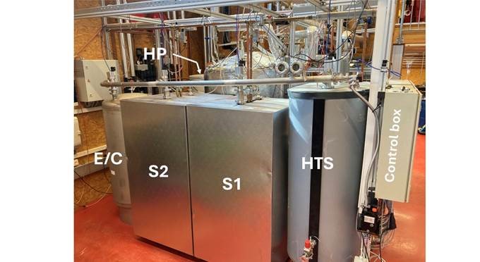
Figure 3: Test stand in the laboratory of AEE INTEC © AEE INTEC / A. Krainer